3
DifficultyArduino Multiple LED Experiment
Take Control of LEDs with an Arduino
Posted by Admin / in Energy & Electricity Experiments
An Arduino microcontroller board makes it very easy to build a circuit to control multiple LEDs. The programming ability of the Arduino also offers a great way to experiment with electronics while learning about programming. This electronics project provides instructions on how to build an Arduino circuit to control multiple LEDs.
Materials Needed
- Arduino Board - Uno used in our experiment
- solderless breadboard
- 3 LEDs (use 3 colors)
- Jumper Wires
- 3 Resistors - 220 Ohms
- Computer with Windows or Mac OS operating system
- USB cable
Building the Arduino LED Circuit
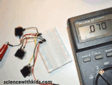
Step 1: One goal of the Arduino multiple LED project is to make it as easy as possible so kids can build the circuit. The best way to make it easy (and safe) is to eliminate using a hot soldering iron. Instead, this Arduino circuit uses a solderless breadboard. Jumper wires are used to make the connections between the LEDs, electronic components, breadboard and the Arduino header pins. First an understanding of how to use a breadboard is needed. A breadboard has tens or even hundreds of holes where wires or electronic components are connected. Within the board different holes are connected electronically. Connections between the holes are organized in rows and columns. If a voltage is applied to a hole in one of these rows, it is also available in any hole in the entire row. The image below shows and example of how a typical breadboard is organized.
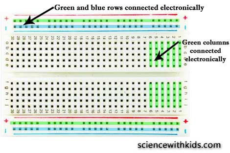
For more information about using breadboards and beginner electronics see our article, Beginner Electronic Experiments for Kids.
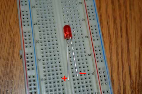
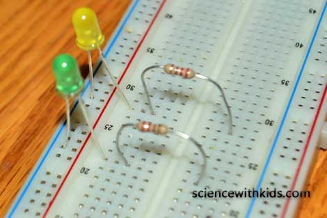
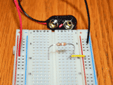
Step 2: Start building the LED circuit. First, find the positive and negative leg of each LED. The positive leg of a LED is the longer leg, also known as the annode. The negative leg of a LED is the shorter leg, also known as the cathode. Place the short leg of each of the LEDs in one of the negative power rails, highlighted as a red row in the photo below. Place the long leg of each LED into one of the inner columns, highlighted in green in the photo below.
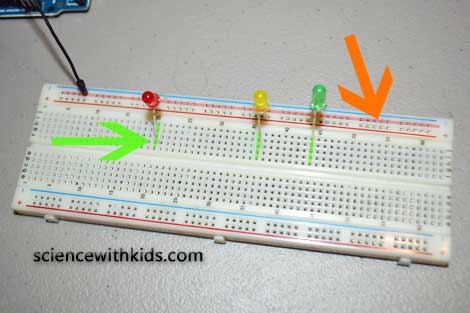
Step 3: Place one end of a 220 ohm resistor in the same column as each LED annode leg. Jumping of the center divider, place the other leg of each resistor into a new breadboard column.
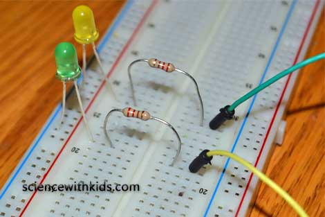
Step 4: Using 3 jumper wires, place one end of each jumper wire into the same column used buy the 220 ohm resistor as shown below.
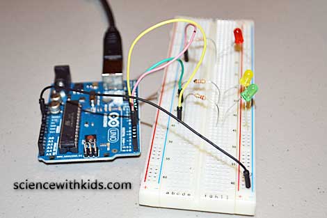
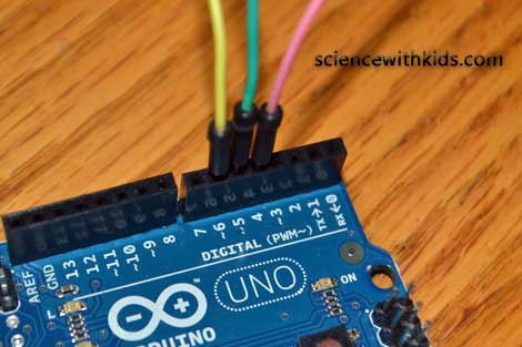
Step 5: Find the digital pins on the Arduino board. Standard Arduino boards such as the Uno and Mega have 14 digital output pins. They are usually labeled 0(Rx), 1(Tx) and 2 through 13. Place one jumper end into the pin header at digital pins 4, 5 and 6 as shown in the photo below.
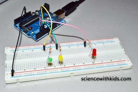
Step 6: The Arduino LED circuit is now complete. Program the Arduino using the code below to control lighting the LEDs.
Programming the Arduino to Control Multiple LEDs
const int redLED = 4;
const int yelloLED = 5;
const int greenLED = 6;
void setup()
{
pinMode(redLED, OUTPUT);
pinMode(yelloLED, OUTPUT);
pinMode(greenLED, OUTPUT);
}
void loop()
{
flash(redLED, 500);
flash(yelloLED, 500);
flash(greenLED, 500);
}
void flash(int pin, int wait)
{
digitalWrite(pin, HIGH);
delay(wait);
digitalWrite(pin, LOW);
delay(wait);
}
Download the Arduino Multiple LED code
Arduino programs, also known as sketches, are based on the C and C++ programming languages. The program layout has three parts including the structure, the values and the functions.
The first part of this code defines the variables used for the Arduino output pins. The variable names redLED, yellowLED and greenLED were used to easily define which color LED was attached to a pin on the Arduino.
Arduino digital pins can be used for either input or output. The pinMode (pin, mode) command is used establish if a pin will be used as input or output. This part of the code sets up the Arduino to use pins 4, 5 and 6 as digital output.
The next part of the code lights up each LED for a set amount of time. The Arduino board processes time code in milliseconds. So a time of 1000 is equal to 1 second. In the example a time of 500 ms was used, which is equal to one-half a second.
What we Learned / Tweaking the Arduino LED Circuit
The Arduino multiple LED circuit help teach both electronic circuits and embedded programming. The Arduino is one of the most popular microcontrollers used with small electronics. It allows a circuit to do different things, if certain things are true. We also can see from the code that Arduino can control the timing of when something can occur. The Arduino also allows connection of multiple circuits and components to one common controller. In our circuit, the three LEDs were actually connected to three different single loop circuits. Normally, we say each LED is in a series. The LEDs are not connected in parallel. The Arduino is used to cycle through each loop (circuit) to make each LED light up in a timed sequence. The code input into the Arduino controls the timing of cycle.
In the circuit, a resistor is needed to protect the LED. Without the resistor, the LED will burn out. The forward voltage value for standard resistors is between 1.8 and 2.0 volts. The typical value of allowable current through a standard resistor is 15 mA to 28 mA (we use 16 mA or 0.016 A in our calculation). The Arduino outputs 5 volts through the output pins on the board. Using Ohm's Law the required resistor value is (5-1.8)/0.016 = 200 Ohms. In the circuit we are using a 220 Ohm resistor to provide a factor of safety. If you want to calculate the actual resistor value needed and it results in a lower resistor value, the LED will be brighter.
Resources:
Resistor standard color coding
Easy LED Circuit (without an Arduino board)
Please select the social network you want to share this page with:
We like you too :)
Thanks for taking time to give us feedback!

posted by Admin
-
6
DifficultyHow to Make a Simple Battery
in Energy and Electricity Experiments
Make a simple battery using coins and other common items.
-
3
DifficultySolar Energy Experiment for Kids
in Energy and Electricity Experiments
Teach kids how light is used to generate electricity in this solar energy experiment.
-
2
DifficultyBeginner Electronics Experiment For Kids
in Energy and Electricity Experiments
This experiment is a good starting point for kids to begin learning about electronics.
-
5
DifficultyLED Solar Circuit Experiment
in Energy and Electricity Experiments
Learn how to make an electrical circuit to power an LED using solar power.
-
4
DifficultyHow to Make an Electromagnet
in Energy and Electricity Experiments
Test the relationship between electricity and magnetism by making an electromagnet.
-
3
DifficultyPower a Light with Static Electricity
in Energy and Electricity Experiments
Use static electricity to power a light bulb!