5
DifficultyElectric Generator Experiment
Posted by D. Rogers / in Energy & Electricity Experiments
The electrical resistor is an important piece of most electronic circuits. Resistors limit the amount of current passing through a circuit. They are useful to protect electrical components in a circuit.
Any material that can conduct electricity is capable of also resisting the flow of electrical current. This electrical experiment uses this concept to allow kids to use their imagination, while learning about electronics.
Materials Needed
- Insulated copper wire (about 5 feet)
- Hallow tube (toilet paper cardboard tube works well)
- Magnet
- Resistor (any value)
- capacitor or another electronic component
- pencil lead
- other material (use your imagination)
STEPS TO MAKE THE ELECTRIC GENERATOR
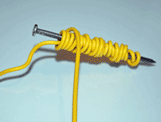
Step 1: Leaving approximately 6" of wire slack, start wrapping the insulated copper wire around the tube.
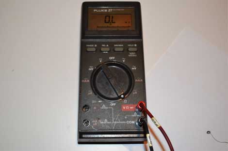
Set the multimeter to the Ohm test reading on the dial.
Step 2: Wrap the wire until about 6" of wire remains
Step 3: Attach both ends of the loose wire to a multimeter or voltmeter. Connect one side to the red (+) probe and the other side to the negative (-) probe. Either wrap the wire around the probes or use alligator clips to attach the wires.
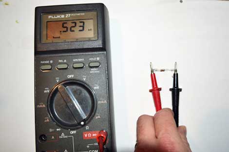
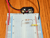
Touch the test probes on each leg of the resistor to test its value.
Step 4: Set the voltmeter (or multimeter) to test for DC voltage.
Step 5: Move the magnet quickly back and forth inside the tube.
Step 6: Observe the voltmeter voltage readings.
Step 7: Set the voltmeter (or multimeter) to test for DC current.
Step 8: Move the magnet quickly back and forth inside the tube.
Step 9: Observe the voltmeter current readings.
MAKE THE LED CIRCUIT TO DEMONSTRATE THE ELECTRIC POWER CREATED BY THE GENERATOR
Step 1: Start with a pencil and a piece of paper.
Step 2: Draw two lines on the paper with the pencil. Make one line thin and the other line thick. You can also try making one line straight and the other line wavy.
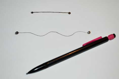
Draw some resistors on the paper with a pencil
Step 1: Set up the multimeter, the same as testing a standard resistor to test resistance. The dial setting is typically the greek letter omega.
Step 3: Touch the negative probe to one end of the pencil line resistor and the positive probe to the other end of the pencil line resistor. It does not matter which lead (positive or negative) is used at either end.
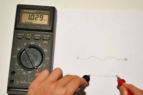
Testing the pencil line resistance value with a digital multimeter
Step 4: Look at the reading of the multimeter and compare it to the results of the standard resistor test. Some multimeters are not auto-ranging. The auto-range feature automatically sets the correct range which the resistor value will show a result. If the meter is not auto-ranging, make sure that the expected ohm range setting is selected before taking a reading or the reading may show up as zero. In the case of a pencil resistor, start with the ohm test setting at its lowest setting.
Step 5: Now try testing the second pencil line and compare the results to the first resistance test. Try testing different points on the pencil line to see if you get different results.
Step 6: This is the point which imagination takes over. Try finding and testing a variety of different materials for the resistance of the material. Hint: materials which conduct electricity work better, but some materials may surprise you. Try to test screws and bolts with different coatings (zinc, brass, copper). Test pencil lead or cut the eraser end off an old pencil and test the lead inside the pencil. Test other electrical components like diodes, capacitors and LEDs. Try anything the kids can image. Test your finger, a standard multimeter does not release enough current to be dangerous.
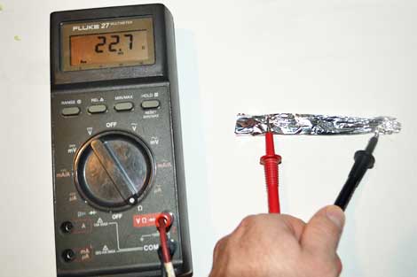
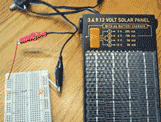
Testing the resistance of rolled aluminum foil with a digital multimeter
Step 7: Test each material for its resistance value and compare the results to the pencil resistor and the standard resistor.
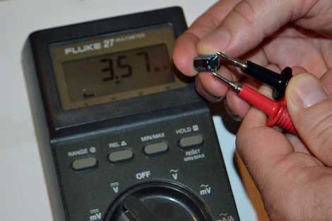
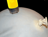
Testing a capacitor's resistance with a digital multimeter
Science Learned
Experimenting with different materials is a great way to understand how different material conduct and resist electricity. Resistors limit or resist the flow of electricity through a circuit. Think of the flow of electricity as the flow of water. If a water system has smooth pipe but a section is added that is rough, the water will flow well through the system until it reaches the rough section. Through this section the flow of water is restricited, reducing the flow. A resistor does the same thing in an electrical circuit. Most standard resistors are made of carbon and glue material. This mixture of material resists flow of electricity. Every material that conducts electricity has at least a little resistance, including the best conductors like gold and platinum. The graphite in the pencil is a decent conductor, but placing the graphite in a line on the paper results in resistance. The longer the pencil line, the more resistance that is created. Think of a longer section that is rough in the water line analogy. Other electronic components have resistance. When electrical engineers design a circuit they must take in account the resistance of these components in their design to make sure they have enough current flowing where they need power.
Resources:
Resistor standard color coding.
Please select the social network you want to share this page with:
We like you too :)
Thanks for taking time to give us feedback!

posted by D. Rogers
-
6
DifficultyHow to Make a Simple Battery
in Energy and Electricity Experiments
Make a simple battery using coins and other common items.
-
3
DifficultySolar Energy Experiment for Kids
in Energy and Electricity Experiments
Teach kids how light is used to generate electricity in this solar energy experiment.
-
2
DifficultyBeginner Electronics Experiment For Kids
in Energy and Electricity Experiments
This experiment is a good starting point for kids to begin learning about electronics.
-
5
DifficultyLED Solar Circuit Experiment
in Energy and Electricity Experiments
Learn how to make an electrical circuit to power an LED using solar power.
-
4
DifficultyHow to Make an Electromagnet
in Energy and Electricity Experiments
Test the relationship between electricity and magnetism by making an electromagnet.
-
3
DifficultyPower a Light with Static Electricity
in Energy and Electricity Experiments
Use static electricity to power a light bulb!