5
DifficultyEasy LED circuit project - Learn how to make a simple circuit to light a LED.
Posted by Admin / in Energy & Electricity Experiments
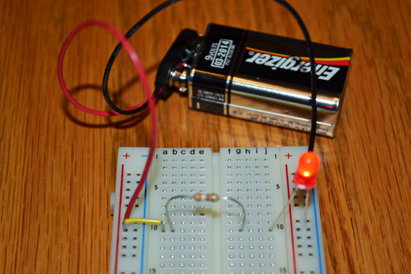
A good starter circuit for kids to experiment with is an LED circuit in series on a breadboard. A circuit is in series when the flow of electricity follows a direct line or completes a simple loop. In this example a single Light emitting diode (LED) will be powered by a battery and light up. In order to power an LED without blowing the diode, a resistor is needed to lower the voltage down to an allowable value.
Materials Needed
- 9 Volt battery
- 9 Volt battery terminal
- Breadboard
- LED (standard LED, red or green)
- Wire or jumper wires
- 390 Ohm resistor (color code: orange-white-brown)
EXPERIMENT STEPS
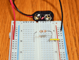
Step 1: To create this simple circuit on the breadboard start with a 9 volt battery terminal. Battery terminals can be purchased at any local Radio Shack or online at radioshack.com, mouser.com or your favorite online retailer.

Step 2: Connect the black, (-) negative wire from the battery terminal to a negative power column on the breadboard. A breadboard typically has a positive and negative power rail on each side of the board. In the example photo, the negative power rail on the right side of the breadboard is highlighted in blue. The positive power rail on the breadboard is highlighted in orange.
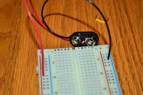
Step 3: Connect the red, (+) positive wire from the battery terminal to a positive rail on the breadboard.
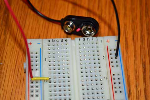
Step 4: Use a jumper wire to connect the positive side of the power rail to one of the breadboard rows. In the example, row 10 was used for the circuit (see photo).
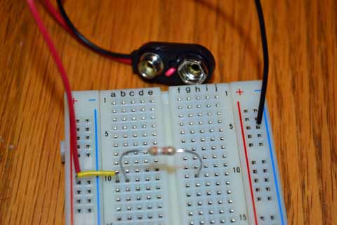
Step 5: Connect one end of the resistor into the same row as the jumper wire was placed on the breadboard in the previous step. Connect the other end of the resistor into the opposite side of the breadboard using the any row. In the example row 10 was used again. There is no positive or negative side on a resistor so it does not matter which end is connected into the negative column.
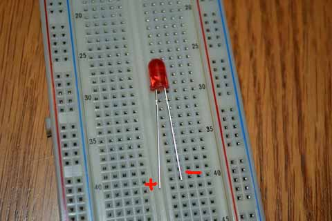
Step 6: Complete the circuit by connecting the positive side of the LED into the same row as the second leg of the resistor placed in step 5. The positive leg of a LED is the longer leg, also known as the annode. Place the shorter leg (negative leg) of the LED into the negative power rail. The negative power rail is any opening in the column where the black power wire from the battery was placed in step 2.
Science Learned
An LED is a Light Emitting Diode. The diode produces light from a low amount of voltage. The voltage must be reduced in this circuit since a 9 volt battery is used in this experiment. Standard LEDs are only designed for a maximum voltage between 1.8 volts and 2.2 volts, depending on the color of the LED and manufacturer. In this experiment a solderless breadboard is used to make the electrical circuit. Using a solderless breadboard increases safety for kids since it elimates the need for a hot, soldering iron. An LED circuit is a great starting electronics project for kids since it is simple to build and produces a light, if produced correctly.
Please select the social network you want to share this page with:
We like you too :)
Thanks for taking time to give us feedback!

posted by Admin
-
6
DifficultyHow to Make a Simple Battery
in Energy and Electricity Experiments
Make a simple battery using coins and other common items.
-
3
DifficultySolar Energy Experiment for Kids
in Energy and Electricity Experiments
Teach kids how light is used to generate electricity in this solar energy experiment.
-
2
DifficultyBeginner Electronics Experiment For Kids
in Energy and Electricity Experiments
This experiment is a good starting point for kids to begin learning about electronics.
-
5
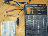
DifficultyLED Solar Circuit Experiment
in Energy and Electricity Experiments
Learn how to make an electrical circuit to power an LED using solar power.
-
4
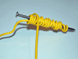
DifficultyHow to Make an Electromagnet
in Energy and Electricity Experiments
Test the relationship between electricity and magnetism by making an electromagnet.
-
3
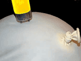
DifficultyPower a Light with Static Electricity
in Energy and Electricity Experiments
Use static electricity to power a light bulb!