2
DifficultyTesting DC Voltage in a Circuit
Posted by D. Rogers / in Energy & Electricity Experiments
Knowing how to measure DC voltage in a circuit is one of the beginner skills for understanding electronics. Teaching kids this skill will help them understand what is actually happening within the circuit. The following procedure will show beginners how to use a multimeter to easily test voltage in a DC circuit.
Materials Needed
- Multimeter
- DC circuit
- Optional
- Breadboard
- 9 volt battery with connector
- Resistor (any value)
- Jump wires
TESTING DC VOLTAGE
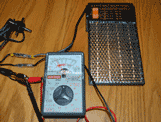
Step 1: Set the multimeter to test resistance. The dial setting is typically the greek letter omega.
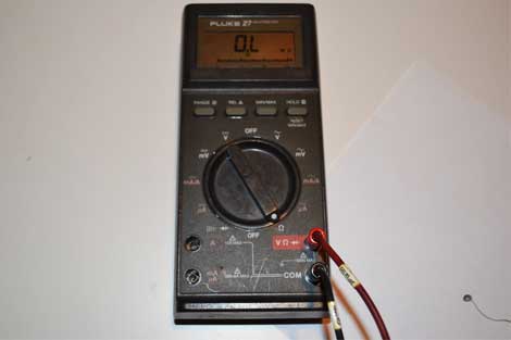
Set the multimeter to the Ohm test reading on the dial.
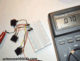
Step 2: Insert the black and red probes into the correct ports. This test is set up as a DC circuit.
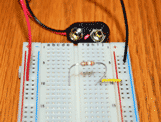
Step 3: Touch the negative probe to one end of the resistor and the positive probe to the other end of the resistor. Polarity (direction of current flow) does not matter for a standard resistor.
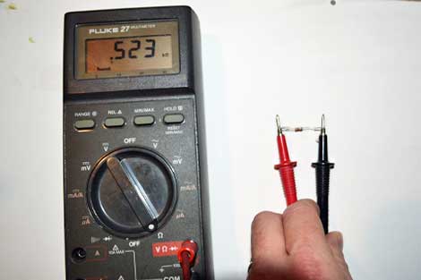
Touch the test probes on each leg of the resistor to test its value.
Step 4: Look at the reading of the multimeter and compare it to the stated resistor value based on the color coding. Some multimeters are not auto-ranging. The auto-range feature automatically sets the correct range which the resistor value will show a result. If the meter is not auto-ranging, make sure that the expected ohm range setting is selected before taking a reading or the reading may show up as zero.
Step 5: If the tested value of the resistor is near the value stated on the color-coding, then move on to the next section. You now know how to test a resistor with a multimeter.
ADDITIONAL INFORMATION ABOUT TESTING DC VOLTAGE
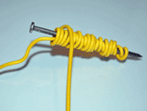
Experimenting with different materials is a great way to understand how different material conduct and resist electricity. Resistors limit or resist the flow of electricity through a circuit. Think of the flow of electricity as the flow of water. If a water system has smooth pipe but a section is added that is rough, the water will flow well through the system until it reaches the rough section. Through this section the flow of water is restricited, reducing the flow. A resistor does the same thing in an electrical circuit. Most standard resistors are made of carbon and glue material. This mixture of material resists flow of electricity. Every material that conducts electricity has at least a little resistance, including the best conductors like gold and platinum. The graphite in the pencil is a decent conductor, but placing the graphite in a line on the paper results in resistance. The longer the pencil line, the more resistance that is created. Think of a longer section that is rough in the water line analogy. Other electronic components have resistance. When electrical engineers design a circuit they must take in account the resistance of these components in their design to make sure they have enough current flowing where they need power.
Resources:
Resistor standard color coding.
Please select the social network you want to share this page with:
We like you too :)
Thanks for taking time to give us feedback!

posted by D. Rogers